Wavetronix Click 510 (communication tester) (CLK-510) - Quick Bedienungsanleitung
Stöbern Sie online oder laden Sie Bedienungsanleitung nach Ausrüstung Wavetronix Click 510 (communication tester) (CLK-510) - Quick herunter. Wavetronix Click 510 (communication tester) (CLK-510) - Quick-reference Guide User Manual Benutzerhandbuch
- Seite / 4
- Inhaltsverzeichnis
- LESEZEICHEN
Inhaltsverzeichnis
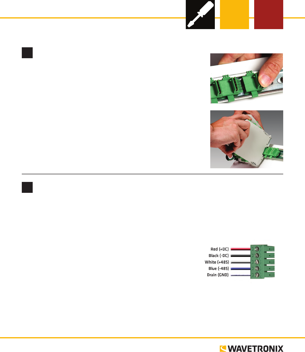
Click 510 Comm. TesterINSTALLER QUICK-REFERENCE GUIDE2 Wire power and communicationIf you are using a Click 200 surge protector with the Click 510, po
3 Use on-device configuration featuresNext, use the device’s conguration features to make sure the Click 510 is wired and working properly. e Click 5
5 Manually set baud rate (optional)Note. is step is optional because if you prefer not to select the baud rate manually, you can also autobaud the de
© 2014 Wavetronix LLC. All rights reserved. Protected by US Pat. Nos. 6,556,916; 6,693,557; 7,426,450; 7,427,930; 7,573,400; 7,889,097; 7,889,098; 7,9
Verwandte Produkte und Handbücher für Ausrüstung Wavetronix Click 510 (communication tester) (CLK-510) - Quick
 (6 Seiten)
(4 Seiten)
(4 Seiten)
(4 Seiten)
(2 Seiten)
(4 Seiten)
(4 Seiten)
(2 Seiten)
(134 Seiten)
(2 Seiten)
(38 Seiten)
(6 Seiten)
(4 Seiten)
(4 Seiten)
(4 Seiten)
(2 Seiten)
(4 Seiten)
(4 Seiten)
(2 Seiten)
(134 Seiten)
(2 Seiten)
(38 Seiten)
© 2020, manymanuals.de. Alle Rechte vorbehalten. | 0.040 s |
 Manymanuals.com
 Manymanuals.de
 Manymanuals.fr
 Manymanuals.it
 Manymanuals.pl
 Manymanuals.cz
 Manymanuals.es
 Manymanuals-pt.com
Kommentare zu diesen Handbüchern